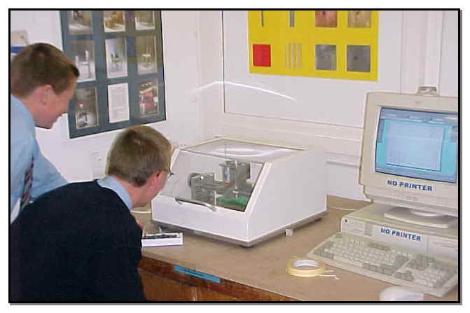
Open Pro-DesktopÔ
From the File menu select New
Choose Design select OK
Maximise the screens.
Choose the Rectangle  tool.
tool.
Move the pencil cursor to the workplane
(Green rectangle with arrow on).
Move to the top left of the green rectangle
with the cursor
Press and hold the left mouse tool and
drag the cursor down to the right to create a rectangle.
Choose the Sketch dimension  tool.
tool.
Move over one side of the rectangle.
(The selected straight goes a light blue).
Select the line by clicking the left
mouse button. (The straight turns red).
Select the opposite straight, hold the
left mouse button down and drag the cursor to create the constraint
outside the rectangle.
Repeat on the other two lines that make
up the rectangle.
To change the value of the sketch dimensions,
Select Constraints  tool.
tool.
Double click on the dimension to open
the properties box and change the dimension.
Enter a length of 150mm and a width of
75mm this will constrain the dimensions of your rectangle.
From the View menu choose Go to, Plan.
To change the shape of the rectangle
to form the bottom of the boat. Choose the Arc  tool
tool
Select the middle of the 75mm line by
pressing the left mouse button once, the line goes orange. Then press
the left mouse button down and drag out the arc.
At the other end of the rectangle draw
the pointed end of the boat.
Choose the Straight  tool.
tool.
Draw two lines from the ends of the rectangle
to form a triangle.
Choose the Select lines  tool
tool
Select the line that forms the base of
the triangle and delete this line also select the line to the right
of the arc and delete this line.
Choose the Select lines tool and drag a box over the whole sketch. (Hold down the left
mouse button and drag over the drawing, the drawing will turn red
when selected)
From the View menu choose Go to, Isometric
Choose the Extrude profile  icon
icon
In the dialogue box enter a distance
of 50mm, check the Add Material and Above workplane.
Select OK.
Choose the Select Faces tool  . This allows you to select and create a new surface to draw
on. This is known as a new workplane
. This allows you to select and create a new surface to draw
on. This is known as a new workplane
Move the cursor over the top of the block,
slightly inside the top face, so that the top face edges are pre-highlighted
a light blue.
Select the face by clicking the left
mouse button. (the line goes red).
Choose Workplane and then New Sketch
Select OK to accept the default names.
Choose View and then Go to, Plan. (It
is easier and more accurate to draw a rectangle on the workplane in
plan view than on the isometric view).
Choose View and then Autoscale (this
makes the block fill the screen area.)
Choose the Rectangle
tool.
Draw a suitable rectangle to form the
sketch of the base of the cabin.
Choose the Extrude Profile tool
In the dialogue box enter a distance
of 40mm, check the Add material and Above workplane.
Select OK
From the View menu choose Go to, Isometric
You are now going to draw a circle on
the top face of the block. This will represent the chimney.
Choose the Select Faces tool.
Select the top face of the cabin (the
lines go red)
From the Workplane menu select New Sketch.
OK
From the View menu choose Go to, Plan.
Choose the Circle  tool
tool
Draw the circle towards the front of
the boat
Select the Sketch dimension tool and move the cursor to the edge of circle. Drag out the
dimension
Select Constraints
tool.
Double click on the dimension to open
the properties box and change the dimension to diameter of 20mm.OK
From the View menu select Go to, Isometric.
Choose Extrude Profile
tool.
In the properties box enter Above workplane,
Add material, and distance 25mm. OK. (This will draw in the chimney).
The next stage is to draw the portholes
in the cabin.
Choose the Select Faces tool
Select the side of the cabin.
From the Workplane menu select New Sketch.
OK.
From the View menu choose Go to, Front
Elevation
Select the Circle
tool
Draw a circle to represent a porthole
near the left side of the boat.
Choose the Sketch Dimension tool and select the edge of the circle and drag out the dimension
of the circle.
Select Constraints
tool.
Double click on the dimension to open
the properties box and change the dimension to diameter of 20mm.OK
Choose the Select Lines tool and select the circle.
From the Edit menu choose Duplicate.
In the dialogue box select Rectangular
and change the X direction number to 3 and enter the spacing as 30mm.
OK
Choose the Project Profile  tool
tool
In the dialogue box check Below workplane,
Through to next face and Subtract material, OK
From the View menu choose Go to, Isometric
to view the result.
Choose the Select Faces tool
Select the top surface of the deck (the
selected lines turn from blue to red)
Choose the Round edges  tool
tool
In the dialogue box enter a radius of
3mm, OK. Extension work: Try using this technique for rounding the
hull of the boat.
To show the finished design in orthographic
views:
Choose Select Lines
tool and drag over the whole drawing
Choose View and select Shaded
Move the cursor into the drawing area
and press the right mouse button. From the menu select Split
Drag the cross hair cursor to the centre
point of your screen and press the left mouse button. (the views can
be sized by dragging the centre cross hair in various directions).
From the File menu choose Save.