| |
On this page, we add a power connection to the components.
Click on any image for a larger, fullscreen view.
Click here to go back to the previous
page
Click here to go to page six
Stage 4 - Adding power connections
|
|
|
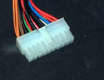
This is the standard ATX motherboard
power connector. |
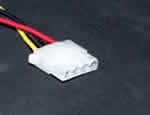
This is a standard peripheral power
connector |
Pentium 4 motherboards need an additional
12v connector |
|
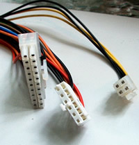
This diagram illustrates the power
connections that are available from most PSUs.
Most PSUs have several peripheral
power connectors, and at least two floppy drive power connectors.
Pentium 4 motherboards need an additional
pair of 12v connectors, using the small square connector,
shown on the right below. |
|
This picture shows the ATX power connector,
the older AT power connector and a Pentium 4 12v connector.
Generally, power connectors are "keyed" so that
they cannot be inserted the wrong way round. The connectors
also have a small locking tab on one side that prevents
the lead working loose once it is connected.
|
 |
|
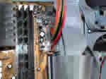 |
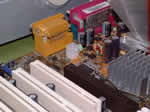
Connect the main motherboard connector, pressing
the connector in until you hear a click. The connector has a small
locking tab on one side |
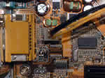 |
Don't forget the additional twin 12v power connector
if you are using a Pentium 4 motherboard. This connector is also
"keyed"
You should now connect a peripheral power connector to each hard
drive, CDROM, ZIP drive etc. The floppy drive will also need connecting. |
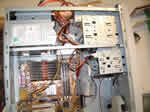 |
Your case will soon become very untidy unless
you plan the route that each connecting lead will take. Try to
work neatly, use cable ties and rubber bands to keep the cables
out of the way.
|
Click here to go to page six
|